Solutions

SOLUTIONS

R&D Solutions:

Lower Frame Assembly:

Improved performance and sustainability!

High-Strength Alloy Cast Steel

EN 10025

The lower frame is made from high-strength alloy cast steel, offering a 20% increase in tensile strength over the original material, extending its service life by 30%.

Force Analysis

During the design process, 3D simulation software is utilized to accurately calculate and verify the strength and fatigue limits of the lower frame assembly.

Integrated Boring and Milling Equipment

Integrated boring and milling equipment is used in production to improve the precision of fit dimensions, enhancing compatibility and interchangeability.

Strength Calculation

Quality control is enforced through quality documentation, with the submission of quality reports. These calculations and verifications include the dimensions, installation position, strength, and stiffness of the lower frame support.

20%
Improve the
Tensile Strength
20%
Improve
Processing Precision
30%
Increased
Service Life
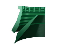
Lower Frame Assembly

Liner Solutions:

Wears

Increase production capacity

Pain Points:

  • The replacement cycle of liners in different crushers within the production process varies, and replacing the liners in any crusher requires a complete shutdown of the production line.
  • The inconsistent replacement times for liners across crushers in different stages lead to frequent system shutdowns, preventing maximum capacity.

Solution:

  • Analyze the ore characteristics and the material properties of the liners in each crusher, and assess production data to match or customize the best wear parts for each crusher in the process. This optimizes the lifespan of the liners in each crusher.
  • Once the liner optimization plan is established, trial the liners and collect data on their lifespan.
  • Based on the lifespan data, establish a synchronized shutdown schedule for replacing all liners, minimizing system downtime and maximizing system capacity.

Case Study:

A tungsten mine in southern China: The crushing process involved three crushers: one for coarse, medium, and fine crushing, respectively. The liner in the fine crusher had the shortest lifespan, lasting only around 10 days. The other crusher liners lasted between 10 and 20 days.

SISUPER designed a customized liner solution for the customer, extending the fine crusher liner's lifespan by 46%, up to 14 days. Simultaneously, the lifespan of the other crusher liners was also improved.

The replacement cycle for the liners was adjusted to a multiple of 14 days, allowing all crusher liners to be replaced during a single shutdown, reducing planned downtime and boosting system capacity.

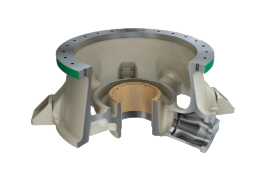
Lower Frame Assembly diagram

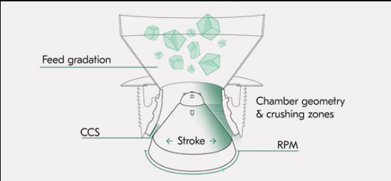
Feed gradation & Chamber geometry & crushing zones

Extending Liner Lifespan

Optimizing Production Efficiency

Pain Points:

  • High Ore Hardness and Abrasiveness: The liners wear out quickly due to the hardness and abrasiveness of the ore, resulting in a short service life.
  • Frequent Liner Replacements: This leads to frequent liner changes at the production site, placing operators under prolonged high labor intensity.

Solution:

  • Ore and Liner Material Analysis: Analyze the properties of the ore and liner material, as well as production data, and match the optimal wear part supplier from the SISUPER database.
  • Production Simulation: Simulate production conditions to verify the lifespan increase of the final product selection. After confirming the plan, provide the product to the customer.

Case Study:

A gold mine in northern China: The site had 4 crushers, and the original liners lasted 5-7 days. Liner replacements were needed almost every working day, placing a heavy burden on the operators.

With SISUPER liners: The liner lifespan extended to 10-12 days, significantly reducing the frequency of liner replacements and the labor intensity for operators.

Liner Product 1 Liner Product 2

Optimizing Production Efficiency

Equipment Challenge:

The equipment was using OEM standard chamber liners, which had low efficiency in operation. The crushers could not reach full load operation until after a certain break-in period, affecting production efficiency.

Solution:

  • Collect various technical parameters during the crusher's operation and analyze the liner chamber profile when the crusher reaches its optimal working state.
  • Analyze chamber profile changes and design a custom liner chamber shape.
  • Simulate production conditions to verify the chamber profile curve. Once confirmed, apply the solution on-site.

Case Study:

A molybdenum mine in northern China: The OEM liners only allowed for 60%-70% efficiency in the initial phase, requiring about 20 hours of break-in time before reaching full load production.

With SISUPER custom-designed liners: Based on customer's operating conditions, SISUPER designed an optimized chamber profile. After using SISUPER's customized liners, the crusher reached optimal working conditions and full load production within just one hour of operation.

Optimization of HP Series Liner Installation Without Filler:

Principle of No-Filler Installation

Increase the length of the matching surface between the head and the liner

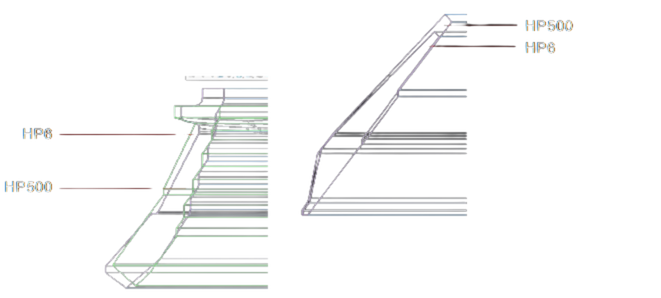
  • Comparison of Original Dimensions Between HP500 and HP6 mantle:
  • The fitting surface of mantle is extended by 240mm, with an increase in mass by 64kg (STD. C).
  • The machined surface of mantel assembly body is extended by 240mm.
  • The machined surface of BOWL liner is extended by 60mm.
  • The fitting surface of concave is extended by 60mm, with an increase in mass by 13kg.

Modification of the Locking Mechanism for BOWL liner:

  • Modification of the Locking Mechanism for BOWL liner.
  • The locking mechanism for BOWL liner has been modified to prevent relative rotation of the liner.
HP Series Diagram

HP6

HP500

Advantage of non-filler installation

Boot operation rate increased

The solidification time of the filler mixture is eliminated, and the downtime of liner replacement and maintenance is effectively shortened.

Service convenience is improved

No need to use filler, and the replacement of liner is faster and easier, which has a positive impact on operator safety.

Production cost reduction

The procurement, transportation and storage processes of fillers can be eliminated, reducing production costs to a certain extent.

More environmentally friendly

There is no need for packing treatment, such as mixing and pouring, and the lining installation process is safer and more environmentally friendly.

R&D Plan:

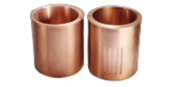
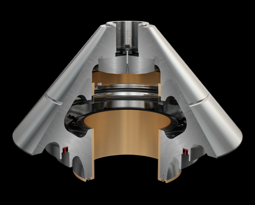
Bushings

Bushings

Customer Pain Points:

  • Large Bushing Clearance: Abnormal swing of mantle and excessive equipment vibration.
  • Poor Wear and Impact Resistance: Rapid wear of the copper bushing, leading to frequent replacements.

Solution:

  • Select the most suitable material based on the function and position.
  • Use centrifugal casting to ensure no shrinkage cavities, air holes, or slag inclusions in the copper bushings.
  • Precision machining to guarantee dimensional accuracy.
20%
Increased Service Life

Customer Requirements:

  • The bushing must have excellent lubrication performance, stable operation, and no casting defects.

Performance:

  • Excellent wear and impact resistance, with longer replacement intervals.
  • Improved lubrication and stable operation.
Reduced maintenance costs

Spare Parts Design Optimization Plan

Locking System Optimization and Upgrade

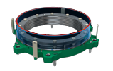
Locking System

Customer Pain Points:

  • Oil Leaks or Cylinder Failures: In case of oil leaks or failures in the locking cylinder, the entire assembly needs to be disassembled, resulting in extended downtime and decreased operational efficiency.
  • Temporary Fixes for Damaged Cylinders: When a locking cylinder leaks or is damaged, it requires a temporary bypass solution on-site, with replacement only possible during scheduled maintenance.

Solution:

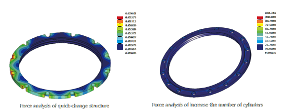
  • Quick-Change Cylinder Structure
  • Replacement of Locking Bladders (HPX Series)
  • Increased Cylinder Count: For example, in the HP500 model, the number of locking cylinders is increased from 12 to 14.
Locking System

CH Series Upper Frame Structure Optimization:

Strengthening the Arm Structure – Principle Optimization

Enhancement 1:

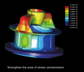
The upper arm is a critical load-bearing part of the entire upper frame. FEA (Finite Element Analysis) revealed that the arm structure is a stress concentration point for the entire upper frame. By increasing its resistance strength, the service life of the upper frame can be directly extended.
Enhancement 1

Strengthen the area of stress concentration

Enhancement 2:

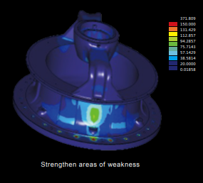
Structural optimization was performed on the reinforcement between the upper flange and the wall to ensure that the axial force generated during crushing is better transmitted from the crossbeam to the upper frame. This minimizes stress concentration and enables the frame to handle more complex working conditions.
Enhancement 2

Strengthen areas of weakness

Enhancement 3:

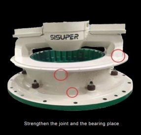
SISUPER uses high-grade alloy cast steel, and after casting, applies a heat treatment process of normalizing, tempering, and quenching followed by natural aging. This process forms a large amount of austenitic structure in the microstructure, significantly improving the tensile and yield strength of the base material. The tensile strength reaches 700-850 MPa (yield strength of 400 MPa), improving product stability.
Enhancement 3

Strengthen the joint and the bearing place

Product Matrix – Mantle Assembly

More Options: Multiple choices for the same product, as SISUPER is committed to providing products best suited to customer needs.

Principle-Based Optimization: Starting from customer requirements, the products are redesigned to deliver stronger and more stable performance.

Product Line
No.
SP01 SP02
Design ★★★★★
Extra Load
★★★
Standard
Work
Condition
High Load Moderate Load
Ore and Rock Hard rock and highly corrosive ore Generally hard rock and stone
Application • Alpine region, high altitude
• Large equipment load, high production requirements
• Overload occurs, and the equipment runs for more than 20 hours
• Medium load, packed feed
• Standard output
• Equipment operation for about 16 hours
Mantle Assembly

Subscribe for
latest newsletter

133 Spintex Road, WH No:11 Accra / GHANA

Make a call

+233 209897564

Sales support

Copyright © 2025. B.M.G Infrastructure Limited All Rights Reserved.